Haskell Ray Tracer, Part I
Part I - Setting everything up
Vector operations
Our first task is to implement vector operations in a reasonable way. If you follow the original tutorial in C++, you will naturally use objected-oriented programming to do this - operator overloading makes things even more convenient. Here we will do something in the same spirit, but using Haskell typeclasses, data constructors and record syntax.
We can start by creating a file called vec3.hs which will contain all the vector-based stuff.
We can then create two data types: one to store vectors and another one to store RGB colors. We could,
for brevity, use the same data type for both, but I think that seprating them makes things clearer
and more readable later on.
module Vec3 where

data Vec3D = Vec3D
            { x :: Double
            , y :: Double
            , z :: Double
            } deriving (Eq)

data Color = Color
           { r :: Double
           , g :: Double
           , b :: Double
           } deriving (Eq)
Listing 1: [Vec3.hs]
Great! Note the use of deriving (Eq) to automatically generate an instance of the Eq
class for our data types. This allows us to verify whether two vectors are equal or not by using the
== operator. For instance, run GHCi and load our file, that is:
Prelude> :l Vec3.hs
[1 of 1] Compiling Vec3             ( Vec3.hs, interpreted )
Ok, one module loaded.
*Vec3>
Now, we test for these basic (in)equality operations:
*Vec3> vecA = Vec3D 2 0 0
*Vec3> vecA == Vec3D 0 1 0
False
*Vec3> vecA == Vec3D 2 0 0
True
Which thankfully worked just fine. However, our program still doesn’t know neither how to make vector operations, such as addition or dot products, nor how to display this information. Thus, our next step is to implement these by hand using a typeclass
class VecOp a where
    (<+>) :: a -> a -> a
    (<->) :: a -> a -> a
    (<.>) :: a -> a -> a
    (<**>) :: Double -> a -> a
    (</>) :: a -> Double -> a
    dot :: a -> a -> Double
    cross :: a -> a -> a
    neg :: a -> a

instance Show Vec3D where
    show (Vec3D x y z) = show x ++ " " ++ show y ++ " " ++ show z ++ "\n"
Listing 2: [Vec3.hs]
with an instance of Show in order to display the vector. Finally, we can also define
the associated operators:
instance VecOp Vec3D where
    (<+>) (Vec3D x y z) (Vec3D x' y' z') = Vec3D (x+x') (y+y') (z+z')  -- Vector addition
    (<->) (Vec3D x y z) (Vec3D x' y' z') = Vec3D (x-x') (y-y') (z-z')  -- Vector subtraction
    (<.>) (Vec3D x y z) (Vec3D x' y' z') = Vec3D (x*x') (y*y') (z*z')  -- Direct multiplication
    (<**>) t (Vec3D x y z) = Vec3D (t*x) (t*y) (t*z)                   -- Scalar multiplication
    (</>) (Vec3D x y z) t = Vec3D (1/t*x) (1/t*y) (1/t*z)              -- Scalar division
    dot (Vec3D x y z) (Vec3D x' y' z') = x*x' + y*y'+ z*z'             -- Dot product
    cross (Vec3D x y z) (Vec3D x' y' z')                               -- Cross product
        = Vec3D (y*z' - z*y') (z*x' - x*z') (x*y' - y*x')
    neg (Vec3D x y z) = Vec3D (-x) (-y) (-z)
Listing 3: [Vec3.hs]
Ok, let’s take a breath. In the first block of code we define a bunch of methods for this class
and their type signatures. For instance, we want the operator (<+>) will be our (+)
equivalent for Vec3D types. Since it takes two vectors as arguments and outputs another vector,
its type signature should be (<+>) :: a -> a -> a. In the same spirit, I used the (admitelly) bad
notation (<**>) for scalar multiplication. In this case we multiply a vector by a scalar,
obtaining another vector, so its type signature should be Double -> a -> a. Let’s test this in GHCi:
*Vec3> vecA <+> vecB
2.0 1.0 0.0

*Vec3> 4 <**> vecA
8.0 0.0 0.0
NOTE: We could in principle overload the operator (+) itself, which is defined in the Prelude. But then Vec3 would need to be an instance of
Num. This is certainly a completely reasonable approach. However, while it makes our code simpler in some places, it also makes it more complicated in others. For that reason I decided to stick with custom operators. We can define the classVecOPfor that.
We will also need some extra functions for now:
length3D :: Vec3D -> Double
length3D (Vec3D x y z) = sqrt(x*x + y*y + z*z)

unitVector :: Vec3D -> Vec3D
unitVector v = v </> length3D v

toColor :: Vec3D -> Color
toColor (Vec3D x y z) = Color x y z

-- | Show instance for Color, in RGB scale from 0 to 255 (numbers should be intergers).
instance Show Color where
    show (Color r g b) = show (round $ 255.9*r) ++ " " ++ show (round $ 255.9*g) ++ " " ++ show (round $ 255.9*b) ++ "\n"
Listing 4: [Vec3.hs]
Now, we proceed by discussing the rays themselves. Two things define a ray: an origin and a direction. Thus, they are written in terms of a scalar parameter $t$ as vector of the form ${\bf P}(t) = {\bf b} + {\bf A}t$. This is pretty easy to write in terms of code:
module Ray where

import Vec3

-- | An origin and a direction define the ray P(t) = A + t b.
data Ray = Ray
         { origin :: Vec3D
         , dir :: Vec3D
         } deriving Show

-- | Evaluates P(t).
rayAt :: Ray -> Double -> Vec3D
rayAt r t = origin r <+> (t <**> dir r)
Listing 5: [Ray.hs]
Thankfully we have the basic toolset to start working on our ray tracer. The first thing we need to do is to figure out how to render/print stuff on the screen. If you check chapter 4.2, Ray Tracing in One Weekend provides a crystal clear explanation on how this procedure works. The steps are essentially the following:
- Position the camera.
- Position a virtual viewport and choose its geometry, such as the aspect ratio of the figure.
- Emit several rays through a virtual viewport originating from the camera.
- Calculate the closest intersection from the origin. This step depends on the ray and on the geometry of the object.
- Compute the color at the intersection point and/or calculate optical effects, e.g., reflection. This step depends both on the geometry of the object and on the material type.
We will go through each of these steps later on. However, let’s forget all about objects, collisions and everything else for now. We will begin by creating a background in our image. Thus, what we need to understand at this moment are just steps 1-3. I will start by adding a couple of new constants to the main file:
-- | Image
aspectRatio = 16.0/9.0
imageWidth = 512
imageHeight = round $ fromInteger imageWidth/aspectRatio

-- | Camera
viewportHeight = 2.0
viewportWidth = aspectRatio * viewportHeight
focalLength = 1.0

originCamera = Vec3D 0.0 0.0 0.0
horizontal = Vec3D viewportWidth 0 0
vertical = Vec3D 0 viewportHeight 0
lowerLeft = originCamera <-> (horizontal</>2) <-> (vertical</>2) <-> Vec3D 0 0 focalLength
Listing 6: [main.hs]
In the first chunk of code we define the properties of the geometry of the image we want to render.
For that, we chose the aspect ratio and the width. Afterwards, we make some definitions for the
camera/virtual viewport. Note that one of the dimensions of the viewport can be arbitrary, but it should
respect the aspect ratio of the figure. Or rather, it is more accurate to say that the geometry of
the viewport determines the dimensions of the final image. focalLength is simply the distance
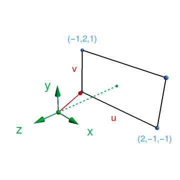
between the camera and the viewport, as you can see in Fig. 1. Finally, lowerLeft refers to the coordinates
of the lower left vertex of the viewport. These variables will completely determine the geometry of
the figure.
Now, we proceed by generating a bunch of rays which are directed towards the pixels in the viewport. We do this as:
-- | Real numbers between 0 and 1.
u = map (/ fromIntegral imageWidth) [0..fromIntegral imageWidth-1]
v = map (/ fromInteger imageHeight) [0..fromInteger imageHeight-1]

-- | A collection of rays which go through the viewport.
rayList :: [Ray]
rayList = [Ray originCamera rayDir
        | vi <- v
        , ui <- u
        , let rayDir = lowerLeft <+> (ui <**> horizontal) <+> (vi <**> vertical) <-> originCamera]
Listing 7: [main.hs]
Remember from Lst. 5 that Ray takes the origin and the direction as arguments, respectively, Thus, each
element in this list is a ray given by ${\bf r}_i(t) = {\bf r}_0 + ({\bf l}_0 + {\bf u} + {\bf v} - {\bf r}_0)t$.
Here, ${\bf u} + {\bf v}$ is simply a point the the projection plane taking the coordinates ${\bf l}_0$
of the lower left corner as the reference. That is, $({\bf l}_0 + {\bf u} + {\bf v} - {\bf r}_0)$
is the direction of the ray passing through the viewport when we take the origin ${\bf r}_0$ as the reference.
The variables u, v in the code are just used to sweep, or “loop over”, through the viewport in the
code. In our particular example, we have ${\bf r}_0 = (0, 0, 0)$ and ${\bf l}_0 = (-1, -2, -1)$.
Finally, we just have to decide how to color the background. If you want to follow the book and use
a gradient background just like I did, the following code should work:
bottomColor = Vec3D 1.0 1.0 1.0
topColor = Vec3D 0.5 0.7 1.0

-- | Colors the background
rayColor :: Ray -> Color
rayColor r = toColor $ ((1-t) <**> bottomColor) <+> (t <**> topColor)
          where
            unitDirection = unitVector $ dir r
            t = 0.5*(y unitDirection + 1.0)

colorList :: [Color]
colorList = map rayColor rayList
Listing 8: [main.hs]
We have to important functions here. The first one, rayColor, provides the rule for coloring
pixels. It takes a ray as an argument and outputs a Color type, which is just a triple representing
a RGB color (in decimal form). For convenience, bottomColor and topColor were both
defined as Vec3D type, in order to allow for vector operations. For that reason we use the
function toColor to implement the appropriate conversion. Note how the paremeter $t$ depends
on the $y$ component of the ray: the ray which goes straight into the middle of the plane has no $x$
and $z$ components, thus $t = 0.5$ and we get a perfect mix between the two colors. Other rays will
have a different ratio between its components, resulting in a vertical gradient since $t$ changes along
the $y$ direction. Meanwhile, the second function colorList just applies rayColor to
the rays in the list rayList. This process results in colorList, which contains a list
of colors for each pixel. So, to wrap things up, we just need to learn how to print this in the
appropriate way. The code for that is quite simple and reads:
main :: IO()
main = do

    -- Metadata
    putStrLn $ "P3\n" ++ show imageWidth ++ " " ++ show imageHeight ++ " 255\n"

    -- Prints the pixels.
    mapM_ print colorList
Note how we preeemptively defined an instance of Show in Vec3.s so print works
with the Color type. And voilà:

We are finally finished with our background! Next we will figure out how to add geometries to our ray tracer. If you want, just check the branch for this part in the repository. Or, if you prefer, just type
$ git clone -b partI https://github.com/alves-gabriel/haskell-ray-tracer.git
into the terminal.